A spool label often states a concise “1.75 mm ±0.02 mm” or “±0.05 mm”. For a one-off prototype print, that number can seem secondary. But when parts are produced in series on several printers and from several material batches, diameter tolerance becomes one of the parameters that determines result stability, the number of recalibrations, and scrap rate.
It is important to understand two things from the start. First, the printer feeds filament linearly, while the part is formed by melt volume, so diameter deviation works not linearly but through the cross-sectional area. Second, tolerance is not a direct guarantee of finished-part accuracy: it is also affected by polymer rheology, moisture, temperature, speed, nozzle condition, and profile settings.
What the tolerance actually means
The nominal filament diameter is 1.75 mm or 2.85 mm. The tolerance shows how far the real diameter may deviate from the nominal value:
- a ±0.02 mm tolerance defines a range from 1.73 to 1.77 mm;
- a ±0.05 mm tolerance defines a range from 1.70 to 1.80 mm.
These are acceptance limits, not a description of the actual behavior of every spool. A ±0.05 mm specification can correspond either to a stable diameter near 1.75 mm or to significant fluctuations between the lower and upper limits. Likewise, ±0.02 mm does not show whether the process is centered around 1.75 mm or whether most measurements sit, for example, near 1.73 mm.
Tolerance is therefore a property of a distribution, not of a single measurement. For a production user, at least three values matter:
- minimum and maximum value;
- average batch or spool diameter;
- the character of fluctuations along the filament length - rare and gradual or frequent and abrupt.
Two materials with the same nominal diameter and even the same stated tolerance can print differently if one has isolated deviations while the other has constant fluctuations.
Why a small diameter change noticeably changes feeding
The slicer calculates feeding based on the assumption that diameter is constant. Material volume is tied to cross-sectional area A = πd²/4, and diameter in this formula is squared. Therefore, the relative deviation in volumetric feed is roughly twice the relative deviation in diameter.
For a slicer set to the nominal 1.75 mm, the geometric effect is:
| Actual diameter | Volume deviation from nominal |
|---|---|
| 1.73 mm | approximately −2.3% |
| 1.77 mm | approximately +2.3% |
| 1.70 mm | approximately −5.6% |
| 1.80 mm | approximately +5.8% |
In other words, a ±0.02 mm field creates a feed variation range of about 4.6 percentage points between the extremes, while ±0.05 mm creates more than 11 points. This is the calculated geometric effect; actual extrusion can additionally change due to feeder gear slipping, filament deformation, hotend pressure, and melt-rate limits.
How this appears in series printing
When diameter “wanders”, the printer over-extrudes and under-extrudes without any settings changes. The effects are familiar:
- bulges and thickening on larger-diameter sections, excess material on top surfaces;
- gaps, incomplete top-layer filling, and weak bonding on thinner sections;
- changes in line width and wall thickness, material buildup near perimeter joints;
- increased hotend pressure, and in extreme cases, nozzle clogs.
On one part this may be unnoticeable, but in production it turns into variation between products: mass, seating surfaces, sealed contours, thin ribs, and mechanical behavior in areas sensitive to incomplete line fusion.
At the same time, feed deviation should not be equated with the same deviation in part dimensions. Excess volume is partly redistributed along the toolpath, while geometry is formed simultaneously by nozzle movement, layer height, extrusion width, and melt pressure. Diameter tolerance is a process-stability parameter, not a standalone forecast of product accuracy.
Ovality is a parameter that is often forgotten
Diameter alone does not fully describe the cross-section. Filament may be 1.75 mm in one direction and noticeably smaller in the perpendicular direction; this is ovality. Oval filament is gripped differently by the feeder mechanism and produces uneven feeding even when the “average” diameter is within specification.
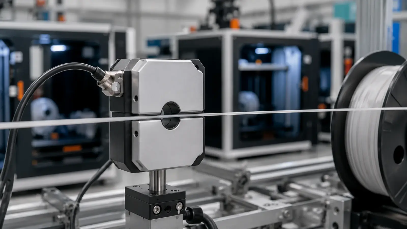
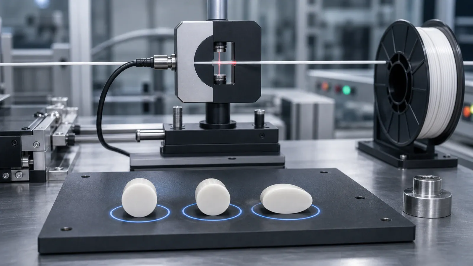
Correct control therefore involves measuring diameter in at least two axes rotated approximately 90° to each other, at many points along the filament. In production, this is implemented with non-contact laser gauges that measure diameter simultaneously from several directions directly on the line and make it possible to track both diameter deviation and ovality.
When ±0.05 mm is enough and when ±0.02 mm is needed
A tighter tolerance is not a goal by itself; it makes sense when the part process is sensitive to flow fluctuations.
±0.05 mm is usually sufficient for prototyping, large-format and decorative products, internal tooling, and test models, provided that the material is stable in average diameter, has normal roundness, and prints with a profile adapted to the batch.
±0.02 mm is appropriate where repeatability is needed: identical parts from different spools, thin walls, critical dimensions, high speed, long continuous jobs, and minimal recalibration. This is especially relevant for print farms running identical jobs on many machines and for flexible or technical materials - TPU, PA/Nylon, filled formulations - that have a narrow processing window.
How tolerance is maintained in production
Stable diameter is not an accident; it is the result of controlling the extrusion process. Modern lines use real-time laser gauges and feedback: the system compares the current diameter with the target and automatically adjusts filament puller speed to keep it within the corridor throughout production. Without this loop, even high-quality raw material produces wider variation.
For a series customer, this means the question is not only which number is stated, but also how consistently the process holds it from batch to batch. Diameter repeatability between batches is just as important as tolerance within a single spool.
What to lock in a B2B order
For contract manufacturing or private label, it is useful to agree on a technical specification before the batch is launched. In addition to material and color, it is worth defining:
- target diameter and allowable range;
- requirements for ovality and batch-to-batch repeatability;
- method and scope of control (two axes, along the entire spool, not selectively);
- spool format, labeling, packaging, and storage conditions;
- expected printing scenario and list of materials (PLA, PETG, ABS+, ASA, TPU, PA), because process sensitivity differs for each.
Bokotech, as a Ukrainian manufacturer of engineering filaments, agrees on these parameters before production starts: selects the material for the part and equipment, fixes requirements for diameter, ovality, spool format, labeling, and packaging, and plans repeatable batches with quality control. If you need a predictable material for a specific production run, technical requirements should be discussed before printing begins.